Author: Lobi

  • What changes as explosive ordnance gets old?

    What changes as explosive ordnance gets old?

    We have previously discussed how susceptible different components of a munition are to ageing. What we will now move forward with is more specifically how the munition can fail as a whole, and what it means for an EOD operator.

    The three main failure points relevant to the EOD operator are failure of the casing, the fuzing mechanism, or the explosive train. Whilst the casing failing will not typically reduce the munition function by itself, a breach of the case will allow for a significant acceleration in ageing as discussed earlier.

    This degradation may mean the munition cannot function as designed, this does not mean that it cannot function at all or is safe. The munition may be susceptible to other forms of initiation, partial function, or even develop an unintended initiation mechanism as a result of some form of sensitisation.

    Casing Failure

    Lightweight casings are much more likely to fail than casings designed to be violently projected or generate a lot of fragmentation, although the fuze and the body may not be equally robust. Heavy cased munitions are likely to be extremely resilient despite surface corrosion.

    Fuzing Mechanism Failure

    Fuzes often have a number of steps to take them from safe for storage through arming and into functioning, including the potential for initiation delays or self-destruct mechanisms. As these are typically removed in a linear series of events, a failure in any one of them can lead in a failure to function as designed. For instance, surface corrosion could lead to increased friction which inhibits a step, or a spring may be too corroded to fire a pin. Self-destruct mechanisms on the other hand can function without some of the usual preceding steps, depending on the fuze mechanism.

    Mechanical Failure

    Mechanical failure in fuzes usually occurs because ageing increases friction which in turn stops the mechanism from actuating as designed. Springs are often made from particularly rust-prone materials and can seize, if subjected to the right conditions, before other components. They are also used for critical functions in arming or firing.

    Usually the seizing up of the mechanism will conserve the arming state the munition was in – an abandoned munition will remain unarmed, a partially armed munition will remain in that state, etc. Sometimes degradation can inhibit a self-neutralisation or self-destruct mechanism too, leaving it in an uncertain state.

    Tripwires

    The high surface area and metal construction of trip wires means that legacy tripwire-actuated mines laid decades ago are almost certain to pose a lesser threat than in the past. Fishing line has been used as a tripwire also, but their degradation over time is less well known.

    Transmission Media

    Some fuzes have hydraulic or pneumatic systems which use a fluid to transfer movement from one component to another. They’re used in some self-destruct mechanisms and many mine designs. Modern Italian mines often use pneumatic systems as part of their shock-resistant design.

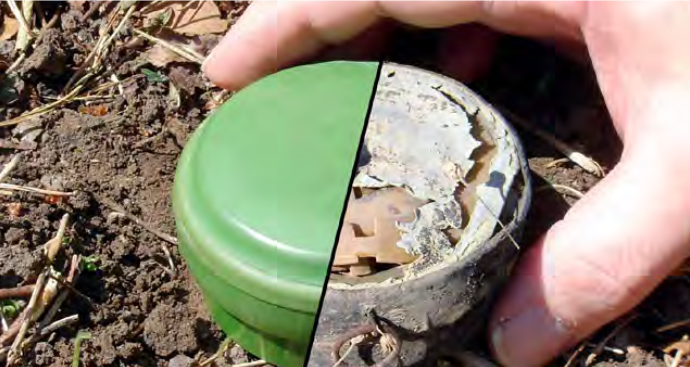
    When the transmission fluid (liquid or air) is not contained, it will prevent the transmission of force and degrade the effectiveness of the system to actuate. In Afghanistan it was found that the Italian TC/6 mines had degraded elastomer pressure plates whose seal had failed around the shoulder, leading them to be inoperable.

    Electrical Failure

    Electrical fuzes need some source to power them, usually a battery. Depending on the way in which the circuit is configured, there may be a significant draining load on the battery or close to none. Different types of batteries also degrade at different rates.

    Reliable lithium batteries can be expected to last over ten years when stored. The battery can degrade in such a way that it still remains over the no fire voltage and poses a threat. Some of the more significant mechanisms of decay include the growth of a resistive layer on the electrode surface (solid electrolyte interphase, or SEI), mechanical cracking of the SEI or electrodes, or thermal decomposition of the electrolyte.

    If the circuit is actively powered, for instance where the power source is running a sensor, the lifespan can be much shorter than the life of the battery (weeks or months). There are cases where the battery is not disconnected per se, but a tiny or no load placed on it and the lifetime can approach the disconnected lifespan. The storage of energy in capacitors complicated this, where normally capacitors bleed voltage but in some cases can hold on to it for an extended period.

    Under field conditions for instance, lithium batteries tested from Spanish SNA submunitions showed full charge twenty five years after manufacture. On the other hand, lithium batteries in a Type 72B Chinese mine from Cambodia have voltages well below the no-fire voltage after thirty years.

    Thermal batteries, where the energy is stored in electrolytes kept separately or in solid phase, can last for an almost indefinite amount of time. Russian shoulder fired munitions with thermal batteries designed to be activated before launching may not last long once activated, but retained perfectly adequate firing voltage fifty years after being produced.

    For 9 V batteries used in VOIEDs, it was sometimes estimated that they would last approximately 36 months or potentially longer if well insulated.

    Failure of the explosive train

    The explosive train has steps between the output of the fuze which triggers the explosive train to begin and the functioning of the main charge. Any step along the train, including igniters, detonators, boosters, and the main charge, can fail. As a result, munitions can remain dangerous even if the main charge would not function.

    • Pyrotechnic compositions: These can become wet and fail to function, but in theory could also become operable again if dried out.
    • Detonators: It is less well studied how these decay. Mercury fulminate gradually decays and lead azide becomes desensitised when damp. Even if the detonating explosive itself is viable, corrosion might separate it from the rest of the explosive train. Just because a detonator is itself de-sensitised, such as lead azide when exposed to moisture, other chemical processes may occur that sensitise it further; lead azide in the presence of water and copper can form cupric azide, a primary explosive too sensitive to use in detonators. This is naturally the highest risk in tropical conditions, although the dangers of using copper in detonator casings for this reason has been understood since World War II.
    • Secondary explosives: these tend to be more stable than primary explosives and are usually not the point of failure. If they do fail, it is likely because of physical degradation (crumbling or plasticiser degradation) which leads to a failure to sustain the explosive train.

    TNT subject to repeated high temperature cycling (above 54 C) may experience exudation. Impurities can interact with the exuded TNT (and its breakdown products like DNT) which in turn sensitises the composition. TNT mixed with grit contaminants (like sand) are more sensitive in drop tests than regular TNT.

    • Propellants: in UXOs the propellants are normally expended, so propellants are typically only present in abandoned ordnance. Nitrocellulose, a common propellant, will decompose under any conditions but faster in hot ones; the O-NO2 bonds break to form nitrogen oxides and auto-catalysis can occur. The nitrogen oxides are absorbed by stabilisers that are added but these are consumed over time which sets the lifespan of the propellant. When stabilisers reach low levels they can auto-ignite and it is thought that this is a common mechanism for ammo storage fires.

    Creation of New Hazards

    New Mechanical Hazards

    Long term, ageing of ordnance leads to loss of functionality and degradation of energetic materials. Despite this, some ageing effects can lead to temporary increases in danger in ways that can be complex and hard to predict. For instance, the retaining pin for a striker could rust through and make the fuze more unstable, although this would likely also occur in parallel to rusting of other components like the striker spring. Exactly how much more or less stable the munition is in the mid-term is hard to determine and will depend on the particulars of weathering and how the fuze is constructed.

    Detecting Metallic Components

    The ability to detect metal components with metal detectors depends on the conductivity of the metal which decreases with rust. This can lead to situations where, specially for minimum metal mines, the munition is undetectable with modern metal detectors. They may nonetheless still be fully functional.

    New Explosive Hazards

    Most new explosive hazards from degradation of EO affects primary explosives, but some secondary explosives are susceptible too. High explosives and alkali materials can form sensitive reaction products which are prone to accidental functioning. Picric acid is also susceptible to reactions with certain metals which form sensitive explosive salts. These picrate salts are de-sensitised with saline solution in fuze immunisation techniques. Picric acid can also form calcium picrate if exposed to cement. TNT which re-crystallises with impurities can more readily form hot spots and is hence more sensitive to being functioned.

    In terms of primary explosives, the most concerning one at present is lead azide which can form hydrogen azide which in turn reacts with metals like copper, zinc, cadmium and its alloys to form highly sensitive explosive compounds. This is prevented by sealing the lead azide in an aluminium line capsule, but degradation can lead to ingress of moisture or contact between the lead azide and copper to form copper azide. This effect is more pronounced in hot/wet climates.

    A fatal accident believed to be attributed to copper azide formation occurred in 2016 in Mali with a corroded Bulgarian-variant M-6 mortar fuze where is suspected that copper azide formed from the contact between lead azide and the copper-containing brass slide in which the detonator was housed. One sign that copper azide has formed is the appearance of a blue mouldy verdigris compound although it is not a conclusive sign.


    The original publication this is based on is from the Geneva International Centre for Humanitarian Demining (GICHD) and can be found at gichd.org under Publications.

  • How does explosive ordnance age?

    How does explosive ordnance age?

    As soon as EO is produced, it begins to age and degrade. Certain components, such as stabilisers in propellants, degrade relatively quickly, whereas others, like thick‑cased projectiles designed to endure extreme firing forces, can remain robust for a long time. The exact speed and nature of the ageing process depend on the construction of the munition and the specific environmental factors it encounters over time.

    The differential rate of decay among components can significantly affect the EOD operator. For example, a munition may be fuzed with a cocked striker whose holding device degrades faster than the coiled spring, causing the munition to become increasingly sensitive over time. Consequently, a munition can be in a highly uncertain state depending on the extent and nature of corrosion.

    This variability also influences detection and identification. Corrosion of ferrous materials generally makes them harder to locate with metal detectors, and a corroded appearance can complicate visual identification.

    As a rule of thumb, munitions designed to experience substantial forces (with thicker casings) tend to be more resilient. Fragmentation munitions are usually more robust than thin‑skinned blast munitions. Nevertheless, thin‑skinned plastic munitions, when protected from UV exposure and harsh environments, can be remarkably durable.


    Primary Explosives

    Different primary explosives deteriorate in distinct ways. Mercury fulminate decomposes into relatively stable compounds, producing a munition that is less likely to function. Tetracene, on the other hand, breaks down in the presence of moisture and temperatures > 60 °C, forming more sensitive compounds such as 5‑azidotetrazole.

    A common primary explosive—lead azide—produces a decay product (hydrogen azide gas, HN₃) that can react with metals like copper, zinc, cadmium, or their alloys to form highly sensitive explosive compounds. This is why lead‑azide detonators are pressed into an aluminium liner when encased in such metals. While some moisture ingress generates hydrogen azide, excessive saturation can actually reduce functionality. Mines discovered in the Falkland Islands are suspected to have suffered from this defect.


    Secondary Explosives

    The main fills and boosters found in ordnance dating back to World I have proven to be very stable. TNT and Comp B recovered from the world wars remain in good condition with minimal deterioration, typically having no significant impact on performance. An exception is picric acid (2,4,6‑trinitrophenol, TNP), which was used as a booster and HE fill but reacts with certain metals to form sensitive picrate salts.


    Propellants

    Compounds such as nitrocellulose (NC) and nitroglycerine (NG) often combined to produce double‑based propellants are initially reasonably stable but decompose over years, especially when exposed to high temperatures. Specific bonds (the O‑NO₂ bond of aliphatic nitrate esters) break down to yield nitrogen dioxide and an alkoxyl radical. Stabilisers are added to these NG/NC formulations, but they typically retain effectiveness for only about 20 years. Over time, propellants become dry and brittle, increasing their susceptibility to ignition from heat or friction. Propellants are generally far more sensitive to ignition than high explosives and are a frequent cause of ammunition‑depot fires.

    In sealed containers (e.g., most rocket motors), the nitrogen dioxide gas remains trapped, raising internal pressure and accelerating propellant breakdown. This can eventually lead to spontaneous ignition or explosion via autocatalytic initiation—a mechanism linked to several major stockpile explosions.


    Materials

    Material selection for munition manufacture balances performance, intended service life, and cost. When exposed to the elements for extended periods rather than stored in a controlled environment, temperature cycling and the generation of decomposition gases can cause pressure changes that crack certain casings, especially plastic ones.

    The most important factor governing casing longevity is thickness, because most degradation is a surface phenomenon. Material type also matters:

    • Aluminium and stainless steel develop protective oxide films.
    • Iron oxide is porous and offers little protection.
    • Copper‑based alloys (bronze, brass) exhibit varying corrosion resistance. Bronze (copper‑tin) performs well in seawater and can be further improved with silicon; brass (copper‑zinc) benefits from tin additions but degrades with higher zinc content.

    Even when rust is encapsulated by another material (e.g., clay), it may retain some protective qualities, so thickness remains crucial and corrosion rates drop if the outer oxide layer stays intact.

    Plastics resist the kinds of corrosion that affect metals, yet they can degrade through UV exposure and heat. Consequently, thickness still matters for protecting the interior. Wood is the least resilient to weathering; even treated wood tends to rot within a few years, affecting wooden mines such as the Russian PMD‑6 or bounding mines with wooden stakes. Nonetheless, if a munition becomes encased in a protective medium, it can persist remarkably long.


    Design and Production

    Design profoundly influences munition longevity, sometimes intentionally. Small gravel mines used by the U.S. in Indochina were encased in cloth and designed to function for only a few days; self‑neutralisation via moisture ingress was a built‑in feature. Conversely, thick fibreglass casings can remain robust for decades.

    Beyond overall case material, welds, seals, and assembly quality also affect weathering resistance. Poor workmanship can dramatically reduce a munition’s durability.


    Damage on Employment and Differential Weathering

    Identical munitions placed a short distance apart can age very differently depending on how they land or are positioned. A munition that lands in a sheltered spot, above the waterline, and sustains no damage can survive far longer than one that breaks, abrades, or experiences harsher micro‑climatic conditions.


    The original publication this is based on is from the Geneva International Centre for Humanitarian Demining (GICHD) and can be found at gichd.org under Publications.

  • Does knowing the chemical structure tell us anything useful about an explosive?

    Does knowing the chemical structure tell us anything useful about an explosive?

    You can calculate a lot about an explosive, relatively accurately, by just knowing its chemical structure. I will describe the steps that you would need to take to get there in broad outline, but the main point to takeaway here is that it is possible. If you really want to nerd out, the process gives you a bit of insight into what kinds of explosives have what properties.


    When you first learn about different explosives they are presented to you in the form of tabulated data; “here is PETN, it has a velocity of detonation of 8,400 m/s, it is a secondary explosive. Here is RDX, it has a velocity of detonation of 8,750 m/s, its brisance is…” To start with, this is probably enough information to employ different explosives in different roles. Perhaps your job does not require you to know any more, but if you have ever asked yourself if you could figure out some of these properties by just knowing what the molecule looks like, then this is for you. The following is summarised from Explosives Engineering by Paul Cooper, Chapter 5.

    Before I describe the process, I should note that the equations can at times be long winded or have funny symbols, but they are all incredibly simple to just plug numbers into a calculator. Some steps require counting oxygen atoms and figuring out if the molecule is fuel/oxidiser balanced. Maybe you need to know a few unusual terms like “aliphatic.” But with a bit of terminology, this process is actually quite simple. The parameters used have been tested on organic compounds, like the vast majority of military and commercial explosives. It is less clear how it relates to peroxides, perchlorates, salts, etc.

    The process goes something like this: first you calculate the theoretical maximum density (TMD) for which you need to know what kind of structure it has and the percentage weight of hydrogen. With that and a specific chemical structure you can calculate the VOD at TMD. You can vary the density to get the VOD at lower densities with the calculated TMD VOD and some empirical constants that can be set to defaults. If you have a mixture you can calculate the detonation velocity by using how much of each explosive (or inert filler, or even air) each of the components occupies. Finally, with whatever detonation velocity you have for your explosive, you can calculate the detonation pressure with a simple formula that takes density, VOD, and an empirical constant that can also be set to a default. All of this gives you single digit % accuracy for most explosives at the end. All it takes is knowing the chemical structure.

    PropertyEquationNeed to knowNotes
    Theoretical Maximum Density (TMD)\(TMD =\) \( a_{i}-k_{i}H\)– Percentage of Hydrogen by weight
    – \(a_{i}, k_{i}\) which are structural group constants which you can look up for each type of structure
    – 2-3% error
    – Hydrogen weight 0<H<6%
    Velocity of Detonation at TMD (\(D’\))\(D’ = \frac{F-0.26}{0.55}\)– Aromatic or not
    – Solid or liquid
    – Numbers of different atoms
    – Number of carbon-oxygen double bonds
    – Number of nitrate ester groups
    – Molecular weight
    – The form factor F is calculated from the variables mentioned and the equation was omitted because it looks complicated even though it is plug and play
    Velocity of Detonation at Lower Density \(D\)\(D = a + b\rho\)– Actual explosive density
    – Empirical constants \(a, b\) OR \(D’\) and \(b\), with \(b \approx 3\)
    Velocity of Detonation of Mixture\( D_{mix}=\sum_{i}D_{i}V_{i} \)– Volume ratio \(V_{i}\) of each component.
    – Can be used even if the component is inert, filler, or even air.
    – Can be used as alternative to the above calculation of lower density VOD.
    Detonation Pressure
    (Also known as Chapman-Jouguet [CJ] Pressure)
    \(P_{CJ}= \frac{\rho D^{2}}{\gamma + 1}\)– Density and VOD of explosive
    – The ratio of specific heats of detonation product gases \(\gamma \).
    – \(\gamma \approx 3\) for typical explosives with densities \(1<\rho<1.8\).

    Let’s apply this to RDX to understand what kind of information this can give us and what kind of error sizes we get when compared to experimentally verified values:

    Image taken from Wikipedia: RDX – Wikipedia

    The first step is to find the theoretical maximum density (TMD), which since RDX is a Group 7 (solid nitrazacyclane or nitrazaoxacyclane) means \(a_{7} = 2.086, k_{7} = 0.093\), and gives:

    \( \rho_{TMD} = 1.833 \)g/cm\(^{3} \)

    This is pretty close to the literature value of \(1.816 \)g/cm\(^{3} \), or 0.94%. From this we calculate the velocity of detonation at TMD (\(D’\)) which, after skipping over the messy looking step where we count atoms and certain by-products, gives us \(F =5.177\) so:

    \(D’ = \frac{F-0.26}{0.55} = 8.94\) km/s

    This is not immediately able to be verified experimentally because the theoretical maximum density is not really achievable, so the next step we take is to use this to calculate the VOD at the tested \(1.76 \)g/cm\(^{3} \). This gives us:

    \(D = D’ -3\Delta\rho=8.72 \) km/s

    The literature value for the VOD at that density is \(8.75 \)km/s meaning the error here is -0.32%. If were to use our calculated value to calculate the pressure of RDX:

    \(P_{CJ} = \frac{\rho D^{2}}{4} = 33.46 \)GPa

    The literature value is \(33.8\) GPa, which means our error is -1.02%. That’s pretty close.

    The short of this is that we have some pretty simple tools that can get surprisingly accurate estimates of some key performance parameters of an explosive with only the chemical structure and some generic constants. Whilst using literature tabulated values will always be easier where they exist, when dealing with novel explosives, these calculations can prove invaluable.

  • Detonations and Deflagrations, High and Low Orders

    Detonations and Deflagrations, High and Low Orders

    Frequently on an explosives range you will hear people comment that a “deflagration” occurred which stopped the expected effect, or a “partial high order” meant that some of the explosives went flying instead of detonating. Do people know what they’re talking about? Usually they could stand to be a bit more precise and this post is aimed to help with exactly that.

    Detonation vs Deflagration

    Detonations and deflagrations end up with the some products but how they get there is markedly different. Basically, a deflagration is a (usually very quick) burning; you get deflagration in an internal combustion engine car to move the piston or the barrel of a gun to fire a bullet. Often deflagration is associated with propellants and pyrotechnics (previously called “low explosives”) because they are designed to undergo that quick combustion but you can cause deflagration in a high explosive too. Deflagration is fundamentally a thermal reaction in that the decomposition of the material happens at the rate at which it heats up and decomposes which happens at the surface and below the speed of sound.

    Detonation is quicker. Specifically, the rate of that decomposition is faster than the speed of sound and is associated with a shock wave.

    When do people get confused?

    With these definitions in mind, where do the lines get blurred? Most of the confusion happens when detonations or deflagrations do not go to plan and a deflagration-to-detonation or detonation-to-deflagration transition occurs. On either end of the spectrum, a full detonation is one where all the explosive is consumed by the detonation and a full deflagration is one where all the explosive is consumed by deflagration (burning). Whilst I have never heard the term used, if you fired an artillery shell and not all the propellant was consumed, you would have had a “partial deflagration”.

    What I hear more frequently is people using the term “partial detonation” and deflagration interchangeably, and I understand why the two get confused: often when a shockwave does not have enough energy to continue the chain reaction and consume all the explosive, the remaining explosive will be thrown by the blast wave, some of which will in turn burn due to the heat of the product gases. So when a partial detonation occurs, some deflagration usually occurs too. But deflagration is just burning, it is not the process of flinging around explosive materials.

    To emphasise: the event that has occurred in a partial detonation is a detonation-to-deflagration transition because some explosives were burnt up after the shock wave failed to continue the chain reaction, but the thrown around explosive material that remains at the end has neither detonated (been decomposed by the shock wave) nor deflagrated (been decomposed by burning).

    Burning to Bang: the Deflagration to Detonation Transition

    If you have followed to this point you know that deflagration is just burning, so this is the same as “burning to detonation.” To understand when this occurs we need to recall that deflagration happens subsonically at the speed of burning at the surface and detonation occurs supersonically at the speed of the shock wave. So how can we go from the rate of burning to a shock wave?

    The answer is that the rate of burning changes depending on the environment, especially the pressure. If you were to take gunpowder and light it in the ground, it would burn far slower than confined in the barrel of a gun. At some point of confinement, the rate of burning will hit a point at which it will exceed the speed of sound and a shock wave will be generated. That is how explosives burn to detonation.

  • TNT Equivalency Factors Are Not Very Good

    TNT Equivalency Factors Are Not Very Good

    The TNT Equivalency Factor is an attempt to summarise the energy output and blast effects of an explosive relative to TNT. An explosive is taken and tested for how much would be needed to achieve the same effect as a kilogram of TNT and given the TNT equivalence factor. In military contexts, its most important use is for estimating safety distances for blast and fragmentation effects. Unfortunately, TNT equivalency factors have a number of flaws that make it poor at doing just that. In this article we will discuss these flaws and present a pathway for better calculations of safety distances.

    The Tests and Literature Values are Inconsistent

    If the aim is to summarise all the different features of an explosive in one number to compare them, it would be helpful if we could all agree on what that number is. Figure 1 shows just how much variation the TNT Equivalence can have in different sources, as much as 50% in some cases with typical variation of 20-30%. I would have failed my safety calculation exam immediately if I had regularly been out by 20-30%, which shows that something is flawed with the approach we take.

    Figure 1: Variations of TNT Equivalency across various sources. [1]

    One of the biggest issues with calculating TNT equivalence that leads to this spread of values is that there is not one single test, and each of the different tests capture a slightly different aspect of an explosive’s effect as it relates to TNT. A series of the most common tests and their shortfalls are discussed by Cooper. [2] The problems identify are typically either:

    1. The test fails to account for the loss of energy from the explosive to the apparatus. Example: the air blast test fails to account for the energy of a higher brisance explosive in shattering the steel casing into smaller and faster fragments.
    2. The test fails to account for the way in which gas products are generated. Example: the ballistic mortar test does not account for non-ideal explosive effects or any explosive that continues to create mechanical energy post-detonation.
    3. The test is a proxy for peak pressure which can be calculated more simply without doing the test. Example: the plate dent test tracks peak pressure well enough that it is used to experimentally verify theoretical value.

    Some reference tables separate two important features of explosives, namely the peak pressure and impulse, to provide two TNT equivalency factors, as can be seen in Table 1 from the US Department of Defense Explosives Safety Board. It is worth noting that, whilst some explosives are relatively consistent, others have significant differences between the pressure or impulse based equivalency factor. HBX-3 for instance is more powerful with regards to pressure but less powerful with regards to impulse than TNT. The number cited more regularly is the peak pressure number (left hand column in Table 1).

    Table 1: Varying TNT Equivalencies depending on the specific aspect measured. [3]

    These inconsistencies between different tests and sources are challenging but in principle solvable if we all agreed on a specific testing protocol. However, the problem runs significantly deeper.

    TNT Equivalency Factors Do Not Scale

    Once the TNT equivalency of some explosive is calculated we should be able to continue our calculations as if we had that amount of TNT instead of the original explosive. Unfortunately the next hiccup in this process is a lot harder to solve: the TNT equivalence factor is different at different distances. This is ultimately because the blast wave characteristics of different explosives are different. Figure 2 shows how the equivalency factors scale at different distances for a few different explosives.

    Figure 2: TNT equivalence at different scaled distances for peak pressure. [4]

    What is important to note from this graph for our purposes is twofold:

    1) The factor that would need to be used at different Z (also known as K) factors is different. So to calculate a safety distance for a K factor of 20 you would need to use a different TNT equivalence factor than for a calculation at a K factor of 100.

    2) The shape of the curves is different for different explosives. That means that the scaling effect cannot be accounted for by just adding a scaling constant, it would change depending on which explosive is being used. Bespoke calculators with these curves pre-programmed would need to be used or extensive tables to look up values for each explosive at each distance.

    In short, because TNT equivalency factors vary with different scaled distances and have different variations for different explosives, a constant factor cannot be used to simplify a calculation without introducing significant error.

    Even Worse for Fragmentation Effects

    The challenge with using TNT equivalence is significantly worse for fragmentation as more factors come into play in terms of the creation and trajectory of fragmentation. TNT equivalence factors are only derived for blast.

    We noted earlier that some of the tests for TNT equivalency, specially the reliable ones, are proxies for peak pressure. When it comes to fragmentation that becomes a problem for deriving accurate safety distances for fragmentation because higher peak pressures change the characteristics of fragmentation significantly in a few ways.

    Energy is transferred to the casing of a munition by three modes: shock heating, strain and fracture, and kinetic energy of the fragments. [2] Each of these steps will take different amounts of energy depending on the peak pressure of the blast wave: higher peak pressure produces greater shock heating, more strain to the casing resulting in smaller fragmentation from the fracture, and higher fragmentation velocity. In turn the size of the fragmentation impacts the distance they travel. Since these features are poorly capture in a TNT equivalence factor, the fragmentation effects are also poorly estimated from calculations based on TNT equivalence factors.

    Improving Blast and Fragmentation Calculations

    First of all, it is clear that blast and fragmentation effects need to be modeled with different factors to understand resulting safety distances. For blast, Locking proposed using the Power Index (PI) as a factor to account for both the heat produced and work available. [4] The PI is based on the explosive power, which is the amount of energy available that can produce an effect on the surroundings. The explosive power is converted to a PI by taking the ratio to the explosive power of TNT. Locking’s paper concludes that Power Index is the most reliable factor for modelling blast effects which in turn means it will be the most useful factor for easily generating blast safety distances.

    As for fragmentation, the two factors which dictate the spread are the velocity of the fragments and the effects of drag. These will vary tremendously not only based on the explosive but also the fragmentation; from the ball bearings in resin of a grenade, to the fragmentation of a steel cased bomb, to the sections of a casing that do not fragment and as projected whole. In principle, all these factors need to be taken into consideration for accurate fragmentation safety distances.

    Some balance between ease of calculation and accuracy of the end result needs to be found to efficiently keep personnel and property safe without overly burdensome safety margins. One possibility is using Gurney and Mott equations to calculate initial frag velocity and drag characteristics. Regardless of the calculation used, it is important to keep in mind the limitations of using traditional TNT equivalency factors to accurately model either blast or fragmentation effects of explosives.

    References

    [1] R. Cheesman, “Definition and Use of TNT Equivalencies in Assessing Loading in Confined Structures,” in ICPS Conference, Manchester, 2010.

    [2] P. Cooper, “Comments on TNT Equivalence,” in International Pyrotechnics Seminar, Colorado Springs, 1994.

    [3] Department of Defense Explosives Safety Board, Blast Effects Computer- Open User’s Manual and Documentation, Alexandria, Virginia: DDESB, 2018.

    [4] P. Locking, “The Trouble with TNT Equivalence,” in 26th International Symposium on Ballistics, Miami FL, 2011.